
ESP monitoring
Surface-based ESA for ESPs, in addition to downhole sensors.
SAM4 adds a surface-based electrical diagnostic layer to existing ESP surveillance. It reads current and voltage from the surface VFD, through the step-up transformer and ESP power cable, to catch electrical-chain and load-pattern changes before they become trips, shutdowns, or premature ESP pulls. No new downhole hardware. Documented in SPE-229389-MS.
No downhole access. Limited condition data. Every unplanned ESP failure risks a pull.
After installation, an ESP is a sealed system. Accelerometers on bearings, oil analysis, ultrasound, manual inspection: none of the surface tools apply here. Operators rely on two data channels: surface electrical measurements and downhole gauges. Downhole gauges are valuable, but they operate in harsh conditions and can degrade, drift, or fail during the run. The surface electrical channel remains accessible for the life of the ESP.
No access after install
Once an ESP is deployed, the motor, seal, pump stages, and cable are inaccessible. Any diagnosis must come from surface measurements or downhole gauges. An unplanned failure means an ESP pull or workover.
ESPs operating worldwide. Average run life: 1–5 years before failure. Average failure frequency: once every 3 years. That is 50,000 workovers per year across the global fleet.
of ESP failures originate in the electrical chain (Springer, 2021; SPE field reliability studies). These are the fault categories that surface ESA is designed to detect. The rest are hydraulic and mechanical failures that require downhole measurement.
minimum workover duration if a rig is already on site. Pull and run the new ESP: 10–14 days. Demobilise: 5 days. Restart: 1 day. If no rig is available, add 1–6 months for mobilisation. Every day is lost production.
Surface measurement through kilometres of cable
ESA uses the motor current and voltage, measured at the surface switchgear or VSD, as a sensor for the entire electromechanical chain. Load changes, mechanical faults, and electrical anomalies modulate the electromagnetic behaviour of the motor, producing detectable patterns in the current spectrum. For ESPs, this measurement happens through two physical filters that do not exist on surface-mounted assets.
Long power cable (1–3 km)
The downhole cable behaves as a distributed LC network. It attenuates high-frequency current harmonics needed for some ESA diagnostics and introduces reflections at cable-motor interfaces. Low-frequency content around the electrical fundamental, which carries most mechanical diagnostic information, survives this filtering. Higher-frequency fault signatures are progressively attenuated with cable length.
VSD switching noise
ESPs are almost always VSD-driven. PWM switching (typically 2–8 kHz) adds electrical noise to the current waveform. Fault signatures must be isolated from this noise through filtering and spectral analysis. In ESP applications, cable reflections from fast switching edges can produce motor-terminal overvoltages up to ~2× per-unit, increasing insulation stress.
Representative SAM4 dashboard view. The cabinet read produces fault classifications with evidence levels and recommended actions. On ESPs, the same workflow runs against surface-side electrical signatures from the downhole motor through the long power cable.
Signal flagged
Expert review
Fault classified
Action recommended
What SAM4 detects on this asset, and where it doesn't fit
One table. Each fault class appears once with its signal path, the strength of field evidence on this asset class, and the recommended use of SAM4. ESP detection works through 1 to 3 km of cable: severe electrical faults transmit cleanly, subtle mechanical signatures attenuate with depth. Field evidence reflects the SPE-229389-MS deployment with ChampionX in the Permian Basin.
| Fault class | Signal path | Field evidence on this asset | Use SAM4 as |
|---|---|---|---|
| Phase loss and voltage imbalance | Direct / electrical. Transmitted cleanly through the ESP power cable. | Pathway established. Cable length does not attenuate direct electrical signatures. | Primary monitoring |
| Process-induced load deviation | Load signature. Sustained load shifts (pump-off, scale, intake change) reach the surface as torque change. | Documented in the Permian deployment. SPE-229389-MS describes the per-event detail. | Primary monitoring |
| Stator winding short indicators | Direct / electrical. Downhole motor stator faults transmit through the cable. | Pathway established across motor-driven assets. | Conditional |
| Rotor bar degradation | Indirect electromagnetic. | Pathway established. ESP-specific cohort still building beyond Permian deployment. | Conditional |
| Gas locking / pump-off | Load step-change. Detected through current dropout and load instability. | Documented detection in the Permian deployment. | Conditional |
| Scale or sand buildup | Long-window load signature drift. | Documented trend detection in the Permian deployment. | Conditional |
| Cable insulation degradation | Direct / electrical. Phase asymmetry and leakage signatures. | Pathway established for trip-precursor signatures. Useful as an early flag. | Conditional |
| Mechanical unbalance | Load signature + 1x running speed. Attenuates through long cable runs. | Pathway resolved on surface assets. Downhole detection conditional on cable length. | Conditional |
| Cavitation-like / gas slug patterns | Load signature + current variance. Pattern visible. Severity not graded. | Pattern observable. Useful as a flag, not a severity measurement. | Conditional |
| Bearing degradation | Indirect electromagnetic + load. Severely attenuated through downhole cable run. | Vibration is not available on the asset. ESA acts as a late-stage indicator only. | Late-stage detection |
| Shaft wear | Late-stage load-pattern signature. Attenuated through cable. | Visible only at advanced wear. Not the right method for early shaft diagnostics. | Late-stage detection |
Outside the envelope: reservoir-side conditions (use downhole pressure and temperature gauges where fitted), pump intake conditions (use intake pressure and temperature sensors), and cable continuity faults requiring trip (use insulation testing and protection-relay data). These are driven by factors other than motor torque and are not claimed by ESA.
What ESA covers. What downhole sensors cover. Where they overlap.
ESPs are the only motor-driven asset with zero physical access after installation. Every diagnostic insight must come from either surface instruments or downhole gauges. Electrical failures account for 50–61% of all ESP failures in published field studies. Though the exact split varies by well conditions and operator. ESA addresses these from the surface. Downhole sensors see the hydraulic and reservoir conditions that ESA cannot. Neither technology alone covers the full failure population.
ESA leads
- Stator winding insulation degradation
- Turn-to-turn shorts and phase-to-ground faults
- Rotor bar damage (induction motors)
- VSD output quality and power supply faults
- Sine wave filter degradation
- Supply voltage unbalance
Both contribute
- Gas locking: ESA sees load loss, downhole sees pressure collapse
- Off-design operation: ESA sees power deviation, downhole locates pump operating point
- Cavitation: ESA detects broadband noise increase, downhole confirms intake pressure below bubble point
- Cable faults: ESA sees impedance change, downhole sees insulation resistance decline
Downhole sensors lead
- Pump stage degradation (direct pressure differential measurement)
- Gas slugging characterisation (intake pressure instability)
- Bearing wear (downhole vibration, where installed)
- Motor thermal protection (winding temperature)
- Reservoir monitoring (absolute pressure and temperature)
Gauge degradation and the surface diagnostic layer
Downhole gauges operate in extreme conditions. Published reliability data shows variable survival across the run. ESA hardware sits in a benign surface environment and outlasts every ESP installation. The exact degradation curve is field- and vendor-specific, but the direction is consistent. ESA does not replace gauges where they survive. It adds a surface layer that runs continuously regardless of gauge state.
| Timeframe | Gauge survival | Description |
|---|---|---|
| At installation | 100% | Full downhole gauge data plus surface ESA. Maximum diagnostic visibility across all fault types. |
| Year 1 | ~65% | In high-temperature wells (>120°C), one-year gauge reliability reported at ~65% in a Saudi Aramco study. Communication dropouts observed when ESP activates (EMI on monoconductor systems). |
| Year 3–4 | Varies widely | Survival depends on temperature class, telemetry architecture, and installation quality. Sensor drift, cable faults, and electronics failure compound over time. No universal industry figure exists for this interval. |
| Year 5+ | ~69% | Five-year survival probability of ~69% reported in a Shell analysis of 952 permanent downhole gauge systems (1993–1998 data). When gauges fail, surface ESA becomes the remaining continuous diagnostic layer accessible at the surface for the run life of the well. |
When gauge telemetry weakens, SAM4 continues
When a downhole P&T gauge fails mid-run, the standard response is to schedule a workover. But if the motor and cable are still healthy, pulling the string is premature. SAM4 data from the surface can confirm that the electrical chain is operating within normal parameters, even after gauge telemetry goes dark.
This gives production engineers a basis to extend the run by 3 to 6 months rather than mobilise a rig immediately. That extension has direct operational value. The production engineer can monitor via SAM4, track degradation trends, and schedule the workover on their terms rather than reacting to a gauge failure.
The case for a surface-based electrical monitoring layer
ESP failures end in a workover. Workovers defer production for weeks at minimum. The question is not whether to monitor, but how to maintain diagnostic coverage when downhole gauges degrade. And how to cover the electrical failure chain that accounts for the majority of ESP failures.
ESA is the only monitoring method that survives the full ESP run life without downhole intervention. It addresses supply-side and motor/cable electrical faults from the surface, fault categories that downhole sensors either cannot detect or detect only through secondary thermal effects. Downhole sensors are irreplaceable for hydraulic diagnosis, gas interference, and reservoir monitoring where they function. Together, they cover the full failure population.
A downhole P&T gauge is the premium in-well diagnostic and degrades in the wellbore. SAM4 hardware sits in a benign surface environment and outlasts every ESP installation. For wells that run without downhole sensors entirely, ESA is the only continuous diagnostic available.
ESA on ESPs is an emerging capability. Detection is conditional on cable length, VSD configuration, and fault type. We position it as a complementary surface layer that reduces the risk of running blind, not as a replacement for downhole gauges where they survive.
Documented detections on ESPs
These are real cases with published detail. We show what we have rather than listing unlinked claims.

Our ESP detection library is growing. As documented cases accumulate, we will add them here. We do not list detection stories without published evidence.
Under 60 minutes at the surface VFD or switchgear. Zero downhole access.
No downhole access required. The entire installation sits at the surface VFD or switchgear. Brief de-energisation while sensors are fitted, scheduled with operations.
1. Open the surface VFD or switchgear
SAM4 installs at the surface VFD or switchgear, the same panel your electricians already access. No confined-space entry, no rig mobilisation, no downhole intervention.
2. Install current and voltage sensors
Current and voltage sensors install on the VFD output or switchgear cabling, upstream of the step-up transformer. Installation requires a brief de-energisation while sensors are fitted, scheduled with operations. No new downhole hardware. No production loss beyond the brief stop.
3. Connect and commission
SAM4 can connect through cellular or approved site communications, depending on field requirements. It does not require integration with SCADA to start monitoring. Monitoring starts immediately, with first diagnostic results within 48 hours of restart.

Industries using SAM4 on ESPs
SPE-documented deployment with ChampionX in the Permian Basin
ESA detection capability on ESPs is conditional on cable length, VFD topology, operating point, and fault type. Rather than average those into a single recall figure, this page reports the deployment that has been independently described in a Society of Petroleum Engineers paper. The cards below show what was caught.
Deployment
- 30 ESPs across the Permian Basin
- Operator: ChampionX
- Run duration: multi-year, ongoing
- Independent reference: SPE-229389-MS (ADIPEC 2025)
Five confirmed early detections across the 30-asset deployment. Lead times range from days to months ahead of VFD trip, depending on fault type.
Confirmed detection mechanisms
- Sine-wave filter degradation, drive-side fault detected before output failure
- Rotor-blade degradation, downhole motor degradation visible from surface current
- Phase-to-ground faults, cable and motor isolation issues caught early
- Broken rotor bars, detected via sideband analysis
- Startup and shutdown anomalies, flagged for operator review
Each mechanism documented individually in SPE-229389-MS. No new downhole hardware required.
Other asset types SAM4 monitors
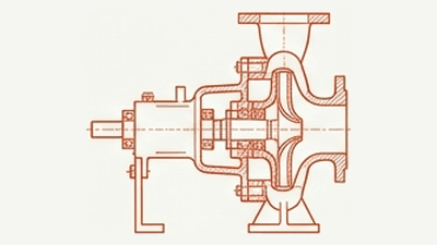
Pumps
Centrifugal pumps in water, chemicals, oil & gas, and process industries.
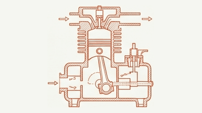
Compressors
Reciprocating, screw, and centrifugal compressors across process industries.
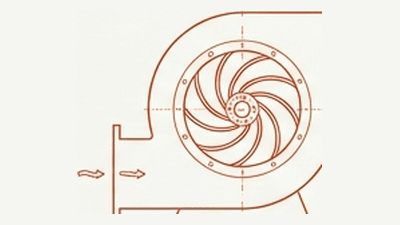
Fans & blowers
Ventilation fans, cooling fans, process blowers, and aerators.
Conveyors
Belt conveyors, screw conveyors, and chain drives.
See SAM4 monitoring ESPs
A 30-minute demo shows SAM4 analysing ESPs from the surface, with real motor diagnostics, pump wear tracking, and run life optimisation data.