
Canned motor pump monitoring
Sealed pump. Sealed motor. The failure mode is a leak.
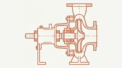
Canned motor pumps remove the shaft seal entirely to handle hazardous fluids: hydrocarbons, acids, refrigerants, hydrogen. There is no bearing housing to mount a sensor on. No shaft to inspect. SAM4 reads the supply current at the motor control cabinet (MCC) to track motor and bearing-rotor condition continuously. No containment breach. No process interruption.
Why canned motor pumps are hard to monitor
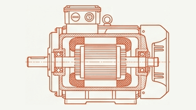
Sealless design means no external shaft seal, and no access to vibration sensors, bearing condition, or rotor position. The sealed can separates the motor windings from the process fluid, but also blocks mechanical and thermal inspection. Failures cascade: bearing wear drives eccentricity, which stresses the can, which fails and floods the motor within hours.
Sensor mounting points on the asset. The drivetrain is sealed end-to-end.
Of canned motor pump failures originate in the sleeve bearings: the component hardest to monitor without embedded position or temperature sensors
Can thickness separating process fluid from motor windings, when it fails, the motor fails within hours
Monitoring through the power cable
ESA measures electrical current and voltage at the motor control cabinet, upstream of the sealed unit. The electrical signal travels via the power cable unaffected by sealed construction. The can material (Hastelloy, Inconel) is non-magnetic; magnetic flux penetrates it. The shorter drivetrain (no coupling, no gearbox) means cleaner baseline spectra. Hydraulic events couple directly from impeller disturbance to rotor rotation to stator current variation.
Electrical faults
Rotor bar breakage and stator winding degradation produce sidebands at characteristic frequencies. Electromagnetic coupling is unaffected by the can.
Load profiling
Dry running, cavitation, and efficiency loss show as step changes or trend deviations in motor current. Direct torque-to-current pathway makes load anomalies visible.
Eccentricity trending
Rotor slot harmonics are sensitive to air gap changes. Small nominal gaps (0.6–1.0 mm) may amplify eccentricity signals relative to standard motors.
Process workflow visibility
The same MCC read produces operating-condition timelines and energy-efficiency curves. One signal, three views: condition, performance, energy. No additional sensors. No process-side instrumentation.
Representative SAM4 dashboard view. The cabinet read produces fault classifications with evidence levels and recommended actions. On canned motor pumps, the same workflow runs against load signatures coupled through the rotor: the can blocks vibration, but lets the electromagnetic signal through.
Signal flagged
Expert review
Fault classified
Action recommended
What SAM4 detects on this asset, and where it doesn't fit
One table. Each fault class appears once with its signal path, the strength of field evidence on this asset class, and the recommended use of SAM4. Field validation on canned motor pumps is in progress; many rows reference physics established across adjacent pump samples. The Methodology section explains how the evidence base grows.
| Fault class | Signal path | Field evidence on this asset | Use SAM4 as |
|---|---|---|---|
| Phase loss and voltage imbalance | Direct / electrical. Resolved at the cabinet from current and voltage symmetry. | Pathway established across motor-driven assets. | Primary monitoring |
| Process-induced load deviation | Load signature. Sustained load shifts and operating-point drift reach the current as torque change. | Pathway established across pump cohorts. | Primary monitoring |
| Mechanical unbalance | Load signature + 1x running speed. Reaches motor current through the rotor. | Pathway established across pump cohorts. | Primary monitoring |
| Cavitation-like operating patterns | Load signature + current variance. Pattern visible. Severity not graded. | Pathway established. Useful as a flag, not a severity measurement. | Conditional |
| Impeller degradation or load shift | Long-window 1x harmonic trend. Detectable where the load actually shifts. | Pathway established. Canned-pump cohort building. | Conditional |
| Dry running | Load step-change. Detected through current dropout. | Critical for canned pumps: bearings and windings depend on process fluid. Pathway established. | Conditional |
| Stator winding short indicators | Direct electrical. | Pathway established across asset classes. Process contamination through can permeation is a real risk on canned pumps. | Conditional |
| Rotor bar degradation | Indirect electromagnetic. | Pathway established across asset classes. Canned-pump cohort building. | Conditional |
| Bearing degradation | Indirect electromagnetic + load. Visible once degradation reaches the motor current. | Pathway established. Process-fluid-lubricated bearings on canned pumps; signal reaches the cabinet through the can. | Late-stage detection |
Outside the envelope: containment can leak (use leak detection, process pressure monitoring, or differential leak alarms), structural defects (no reliable electrical or load expression), and cavitation severity grading (pattern visible, severity calibration out of scope; use hydraulic instrumentation if grading is required). A can breach is a mechanical containment failure with no torque or current signature before it happens, so it is not claimed by ESA.
ESA alongside existing canned motor pump instrumentation
No single technology covers all failure modes on a sealed pump-motor unit. The question is which combination provides the best coverage for your risk profile.
ESA (from MCC)
- Broken rotor bar detection (only sensorless method)
- Stator winding trending (continuous vs periodic testing)
- Retrofittable to any canned motor pump, no access to sealed unit required
- Load profiling and efficiency tracking
- Eccentricity trending via rotor slot harmonics
Overlap
- Dry running detection (ESA current step-change + process flow/pressure)
- Operating condition monitoring (ESA load profiling + process parameters)
- Eccentricity trending (ESA harmonics + embedded position sensors where fitted)
- Cavitation signatures (ESA noise floor + hydraulic performance metrics)
Embedded sensors & Process monitoring
- Precise bearing wear measurement (E-Monitor by Sundyne, MAP by Hermetic-Pumpen, and similar embedded position sensors)
- Can integrity monitoring (barrier fluid conductivity)
- Winding temperature (embedded RTDs)
- Process fluid condition (moisture, particle count)
- Pressure and flow rate
ESA does not replace embedded sensors on safety-critical applications. It provides continuous electrical monitoring that fills gaps: especially on units without E-Monitor or MAP systems, and on failure modes (rotor bars, winding condition) that no embedded sensor detects.
Under 60 minutes. No pump access required.
1. Open the motor control cabinet
SAM4 installs at the MCC, the same panel your electricians already access. No process-side access, no breaching containment, no work near the sealed unit.
2. Clip sensors onto motor supply cables during a brief de-energisation
Current and voltage sensors clip directly onto the existing cabling. The motor is briefly de-energised for the clip-on, then re-energised. No wiring changes. The pump and seal envelope are never opened.
3. Connect and commission
The SAM4 gateway connects via cellular (4G/LTE). No dependency on your IT network. Monitoring starts immediately, with first diagnostic results within 48 hours.

Where field-validated proof lives today
Field validation on canned motor pumps is building. The closest field-validated evidence sits on adjacent pump pages, where ESA reads the same MCC pathway through the same drivetrain physics.
Centrifugal pump cohort
22 published case studies across centrifugal process pumps. Per-fault evidence spanning electrical unbalance, cavitation, blockage, and bearing-side detection. The drivetrain physics that couples impeller, rotor, and stator current is the same as on canned motor pumps; the difference is the can material between rotor and stator, which is non-magnetic and electromagnetically transparent.
Submerged sewage pump cohort
1,213 scored events in the 12 months ending May 2026. 98.5% recall, 2.0% false-alert rate. The largest pump cohort overall, with field performance metrics published under our reporting rules. Same MCC-side physics as canned motor pumps, with mature evidence on hydraulic load anomalies (clogging, dry running) that map directly.
Other asset types ESA monitors
Pumps
Centrifugal pumps in water, chemicals, oil & gas, and process industries.
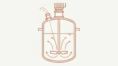
Agitators & mixers
Reactor agitators, tank mixers, and blenders.
MV motors
Medium and high voltage motors in critical processes.

LV motors
Low voltage motors across all industrial applications.
How this page is validated
Field validation on canned motor pumps is in progress. The pathways above have a clear signal path inherited from comparable pump architectures, but field evidence on this asset is still building. Per-fault recall and false-alert percentages will be published once the canned-motor-pump sample reaches the threshold set in our reporting rules. The cards below describe how the evidence base grows and what evidence is available today.
How the canned-motor-pump evidence base grows
- Each alert SAM4 raises on a canned motor pump is followed up against customer-confirmed outcomes
- Cases are scored independently: detected, missed, or false alert
- Pathways resolved on comparable pump architectures inform initial scoping and severity bands
- Field evidence on this asset moves from a clear signal path to case-by-case proof to a published metric as the evidence base grows
What evidence is available today
- Pathway analysis grounded in three-phase induction motor physics
- Resolved patterns on comparable pump architectures (centrifugal, submerged sewage)
- Fleet-level review of comparable-cohort performance available on request
- Validation plan for canned-pump deployments shared with qualified technical evaluators
Explore ESA monitoring for your canned motor pumps
Talk to an engineer about how ESA works alongside your existing instrumentation. We'll map your fleet, identify monitoring gaps, and show where ESA adds coverage.
Frequently asked questions
The canned-motor-pump sample is below the threshold set in our reporting rules, which require an adequate sample of scored field events before publishing per-fault recall percentages. The pathways on this page have a clear signal path and are informed by comparable pump architectures (centrifugal, submerged sewage), though field evidence on canned motor pumps is still building. Field evidence on this asset moves from a clear signal path to case-by-case proof to a published metric as the evidence base grows. Engineers running early-deployment scoping receive the comparable-asset evidence and the validation plan directly. See the Methodology section above.
ESA does not replace embedded position sensors on safety-critical applications. Embedded systems give the most precise bearing wear and rotor-position measurement on units they're fitted to. ESA is continuous, retrofittable to any canned motor pump without breaching containment, and detects failure modes (rotor bar degradation, stator winding faults) that no embedded sensor catches. The two technologies are complementary: embedded for bearing-side precision where fitted, ESA for fleet-wide continuous coverage including units without embedded systems. See the Monitoring architecture section above.
SAM4 sensors install at the motor control cabinet, which sits in the safe-area control room rather than the hazardous-area pump environment. The MCC location means the SAM4 hardware itself does not need ATEX certification for most canned-motor-pump deployments. For specific deployments where the cabinet is in a hazardous zone, talk to an engineer about certified installation options. See Security & network architecture for the full installation envelope.